Making Intelligent Notes & Equations
When calling out holes on drawings, best engineering practices are to dimension holes in true profile views. SolidWorks will only let you place place hole notes on arcs. But sometimes on a complicated drawing, creating an extra auxiliary view just to show a hole callout is not desired and can really clutter the page.
You can just plop a note attached to a hole, but what if your hole diameter changes? Are you sure that you will remember to go update that note? I’m not. This tip will show you how to create a semi-smart note that will update with changes to the hole size.
First, let’s check our drawing specification. Here we use ASME Y14.5M-1994, and section 1.4 (Fundamental Rules), paragraph (g) states:
"Dimensions should be arranged to provide required information for optimum readability. Dimensions should be shown in true profile views and refer to visible outlines."
Note that the word "should" denotes that this is the preferred practice. If instead "shall" was used, there could be no deviation.
So okay, we know what the best practice is. But we also want to try to keep our drawing as simple as possible, eliminating unneeded views, especially on a busy drawing.
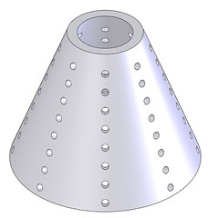 So say we have a part that looks like this. Any type of cone, ogive, or irregular surface that has holes normal to the surface will usually give you this issue.
 Because in a orthogonal view of this part the holes are essentially ellipses, SolidWorks will not let you place a hole note, but it is smart enough to know that there is a hole there to pull the information from.
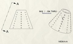 So, you will have to create an auxiliary view to be able to call out the holes, as shown here. In many cases, the only thing shown in this view is the hole callout. Ofttimes it would be preferable to dimension the holes in the orthogonal view, as shown in the next image.
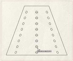
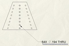 Here, we have attached an annotation to one of the hole edges in the orthogonal view. To get the information to populate the note, we have to go back to the model to get the dimension name. The format is:
64X
where "Thru Hole Dia." is the name of the dimension, "Sketch 2" is the name of the sketch defining the hole size, and "foo.SLDPRT" is the name of the part file. This will allow the hole size to update if the hole is changed to say, a #10 hole. You are somewhat limited, as I know of no way to capture the number of holes in this particular instance, as the hole was first linear patterned 8X, and then circular patterned 8X. Note that you can capture one or the other by using "D1@[email protected]" or "D1@[email protected]". Of course, if you create all the holes in the same hole feature, it is very easy to capture this information in your note.
Also, by using this variable format for referencing part and assembly dimensions in other files, you can also construct intelligent cross-file equations!
So try this technique yourself and see how comfortable you are with it. Hopefully this tip will help you more easily document your designs and provide more flexibility when referencing external files.
![]()
![]()
![]()
![]()
![]()
![]()
![]()
![]()
![]()
![]()


Pingback: Making Intelligent Notes & Equations | CADFanatic()